Creo Drawing a Centerline Creo sometimes will not provide a centerline for your orthographic layout because it does not see it as a full 360 degree arc. The basic Centerline tool allows you to pick two points and it automatically creates a line on the centerline layer which by default is layer AM_7.
Line Creation
If you turn this off prior to placing any views NX will not create the centerlines automatically until you re-check the box.
. The second option for Auto Insert centerlines is Centerlines navigating to it is the same as listed above. If this is toggled ON then when you place a Drawing view the system will attempt to create any 2D or 3D centerlines in the view that it can. In a drawing document click Centerline Annotation toolbar or click Insert Annotations Centerline.
You can select either the tool or an entity first. If the line type for center marks and centerlines is set to continuous all. If you have one hole and want a PCDPCR highlight the view select sketch RMB one.
Unigraphics has a centerline tool in the drawing mode that does it with a couple of mouse clicks. JavadM Mechanical OP 16 Sep 15 1619. We recently have gone from Creo 2 to Creo 3 M20.
To insert centerlines manually. If in doubt leave them out as too many centerlines will look confusing. Annotation of hole centerlines in drawing mode.
Change the line type to the same as a normal centerline. In a drawing document click Centerline Annotation toolbar or click Insert Annotations Centerline. The Centerline PropertyManager appears.
If your feature is less than 360 degrees then you will need to manually draw in a centerline. Although there isnt a built-in function to generate centerlines for curved parts here are alternative ways to do it. Change to datum tab.
I first drew out the straights separating each track by 2 then I used the stick to trace the curves inserting nails into the foam to hold it in the correct position. Centerlines in your SOLIDWORKS Drawing have always been easy to add in and thats fine if you are done with your part but what if it changes. In the Style and Standard Editor change mark gap extension and other attributes.
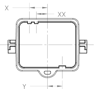
Is there a way to put centerlines between holes in detail drawing views. And theres an option titled Centerlines. In general use centerlines sparingly in isometric drawings.
In Creo 20. Manually draw a centerline. Once the views are in their final place then you are ready to draw the centerline.
Draw the curved part as a 3D model using SWEEP command. To draw the centerlines I used a long aluminum straightedge and a bendable stick that I picked up at Home Depot for a couple of dollars. Draw a sketched curve using the project centre as the arcs centre.
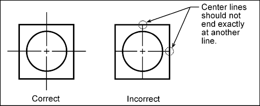
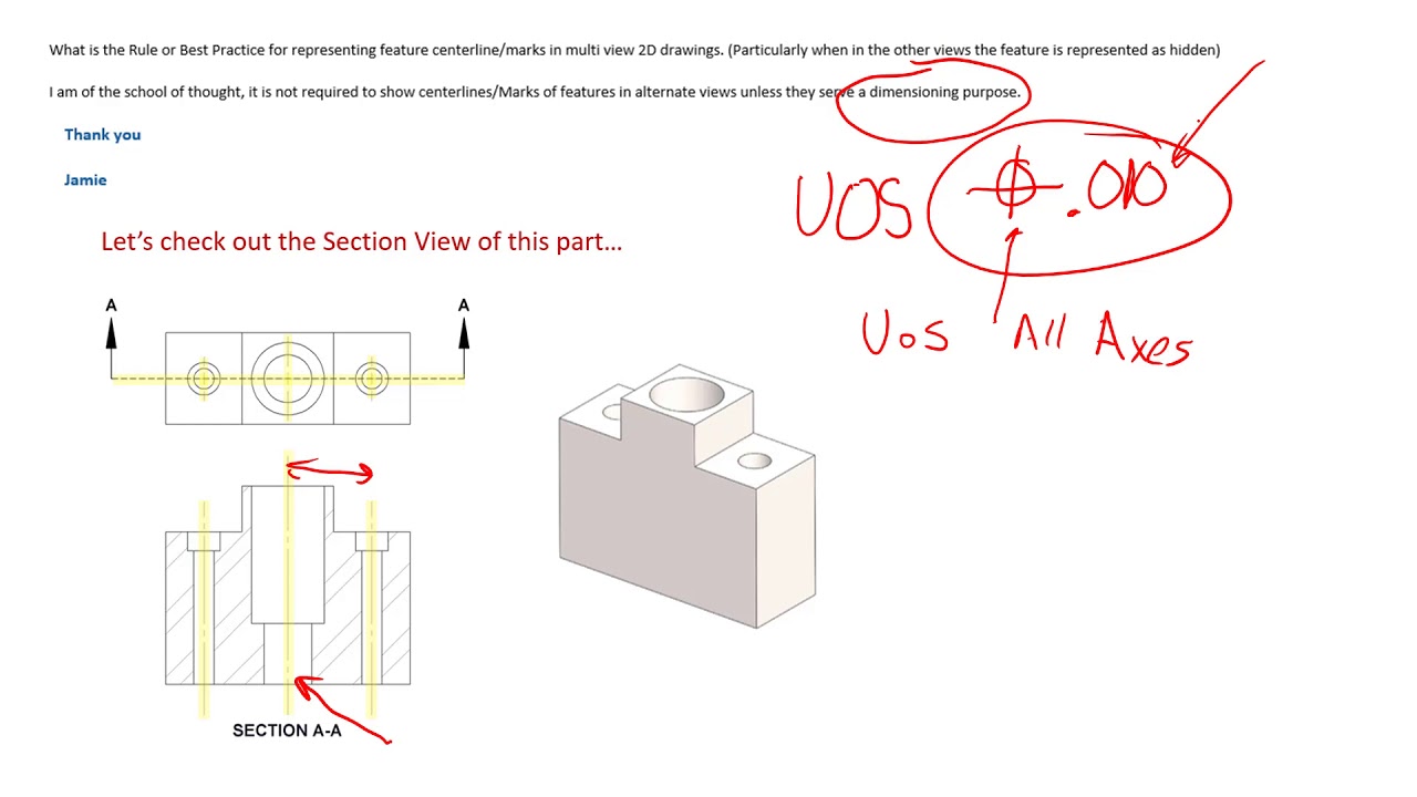
Draw centerlines locating the center of a hole only if they are needed to indicate symmetry or for dimensioning. I want to show the hole centerlines of the various parts. I didnt see a community for drawing so here I am.
With this trick Im going to show you how you can add the centerlines using your models sketch. You could constrain them to specific geometry in that view such as the center point of a hole. Add a datum point in modeling along one of the edges at a ratio of 500 and then add datum axis through that point and normal to the surface.
The first auto insert option with regards to centerlines is the first in the list Center marks-holes-part. In Creo 2 I would pick the views pick the Show Model Annotations button under the Annotate ribbon then pick. Of the curved lines and select Project EdgeGeometry to get the centre point.
Preferences - View - General. Place your views 2. Sometimes the centerlines are fine other times you must rebuild them.
Centerlines and centermarks on drawings. The Centerline tools are located on the ribbon Home tab Draw panel. Select the centrelines click OK.
Is there a way to do this I. Manually draw a centerline between the curved paths. Coming for a Solid works background you could sketch centerlines between holes in any drawing view.
The Centerline PropertyManager appears. Right-click a center mark or centerline and select Edit Center Mark Style. Select the view or the feature in the model tree Right-click show annotations.
This option will add centerlines to your holes visible when straight on a view like the drawing demonstrated below. Look under View - Common - General and you should find a setting under Workflow that controls the creation of Automatic Centerlines. Pretty cool but way too many steps to add a centerline.
It overshoots the pick points by a predetermined amount so your picks dont necessarily have to be exact. Edges then select each hole and select Create. I have created a drawing of a small assembly.
Now toggling this OFF before manually placing your Drawing views will prevent them from being created.

Manually Add A Centerline Inventor Autodesk Knowledge Network
Automatically Inserting Centerlines Within A Solidworks Drawing Computer Aided Technology Https Www Cati Com

Centerline Annotations 2018 Solidworks Help
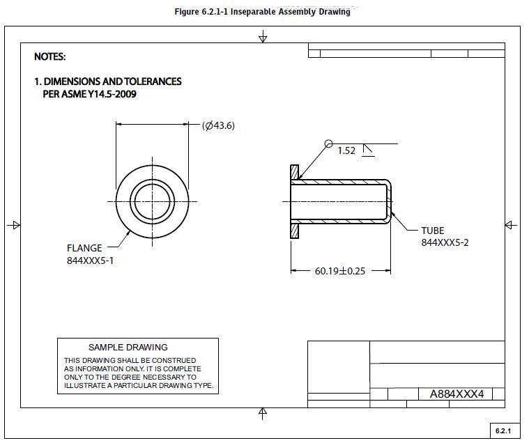
Standard Covering Centerline Usage Without A Dimension Drafting Standards Gd T Tolerance Analysis Eng Tips

About Center Marks And Centerlines Autocad Lt 2021 Autodesk Knowledge Network
Centerlines On Engineering Drawings And How They Should Be Used Correctly Youtube
Centerline Use Drafting Standards Gd T Tolerance Analysis Eng Tips
Gd T Tips Centerlines
0 comments
Post a Comment